Chapter 10
10.1 Introduction
The Root Locus method is a graphical technique used to plot the location of the poles of a closed loop system as one of the system parameters is varied. This technique is used to provide a measure of the relative stability of a system, as well as to determine appropriate parameter values, which will yield suitable root locations. In the general case, the open loop transfer function is G(s)H(s). However, typically an equivalent open loop system is analyzed, with H(s) = 1. Root Locus equations below are derived for such a case, without a loss of generality (see the notes on the equivalent unit feedback loop).
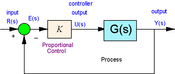
Consider a simple unity feedback system, such as in Figure 10‑1, with the variable proportional controller gain K. The closed loop system transfer function and its characteristic equation are as follows:
[latex]G_{cl}=\frac{Y(s)}{R(s)}=\frac{KG(s)}{1+KG(s)}[/latex]
[latex]1+KG(s)=0[/latex]

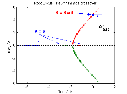
The location of closed loop poles can be traced by plotting them on the same plot for different values of proportional gain K, as shown in Figure 10‑2. The resulting plot is called the Root Locus plot. The Root Locus technique can be used for an s-domain based analysis and design of control systems.
The poles of the closed loop system are determined by solving the characteristic equation:
| [latex]1+KG(s)=0[/latex] | |
| [latex]\rightarrow G(s)=-\frac{1}{K}[/latex] | |
| [latex]\rightarrow |G(s)|\angle G(s)=-\frac{1}{K}[/latex] | Equation 10-1 |

Therefore, for the points in S-domain to belong to the Root Locus, it is necessary that two equations be satisfied:
| [latex]|G(s)| = \frac{1}{K}[/latex] | (magnitude criterion) | |
| [latex]\angle G(s)=180^{\circ}\pm n360^{\circ}[/latex] | (angle criterion) | Equation 10-2 |
So, for any gain K, we can solve the above equations to determine the closed loop system pole locations. Notice, if we allow the controller gain to vary, i.e., [latex]0

