Chapter 13
13.7 Examples
13.7.1 Example
Consider a following closed loop system where a Lead Controller is to be designed such that the system will have less than 10 % overshoot and a Settling Time of 2 seconds. Note that the uncompensated system is unstable!!


13.7.2 Example
Consider a following closed loop system:
Part 1: Evaluate the system closed loop step response based on the provided open loop frequency response.
Part 2: Design a Lead Controller such that the Percent Overshoot is less than 20 %, Settling Time is less than 4 seconds and the steady state ramp error no larger than that for the uncompensated system.

13.7.3 Example
Consider again the control system in Example 13.7.3 above. Design a Lag Compensator for this system such that the percent overshoot is less than 20 % and the steady state ramp error is no larger than that for the uncompensated system.
13.7.4 Example
Consider again the same system Example 13.7.3 above, but with a different controller, this time it will be the Lead-Lag Controller. Design it for this system so that the Percent Overshoot is less than 20 %, settling time is less than 4 seconds and the steady state ramp error no larger than that for the uncompensated system.
13.7.5 Example
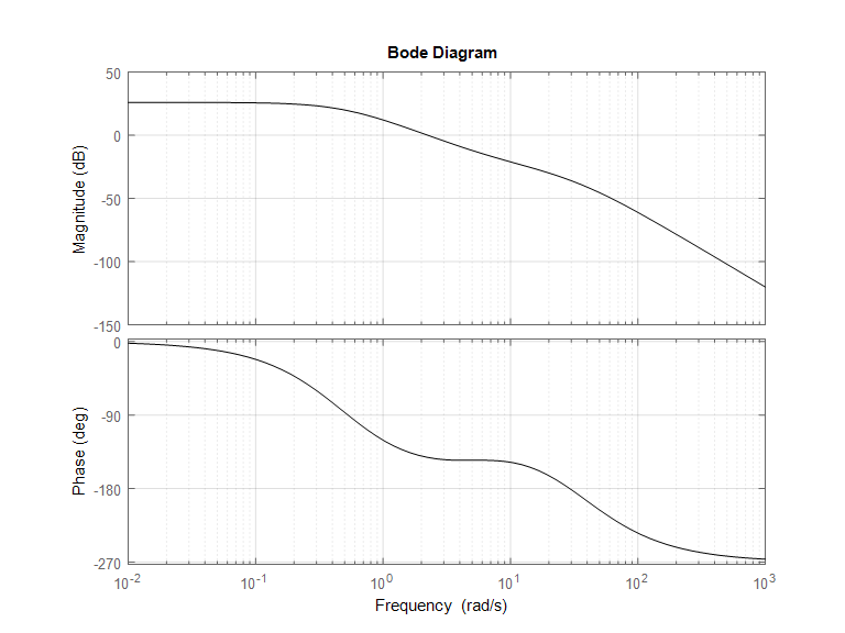
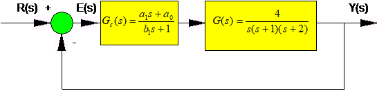
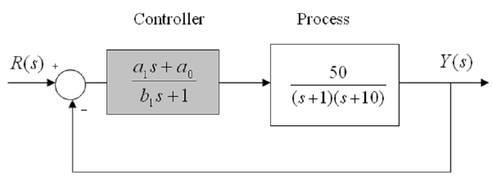
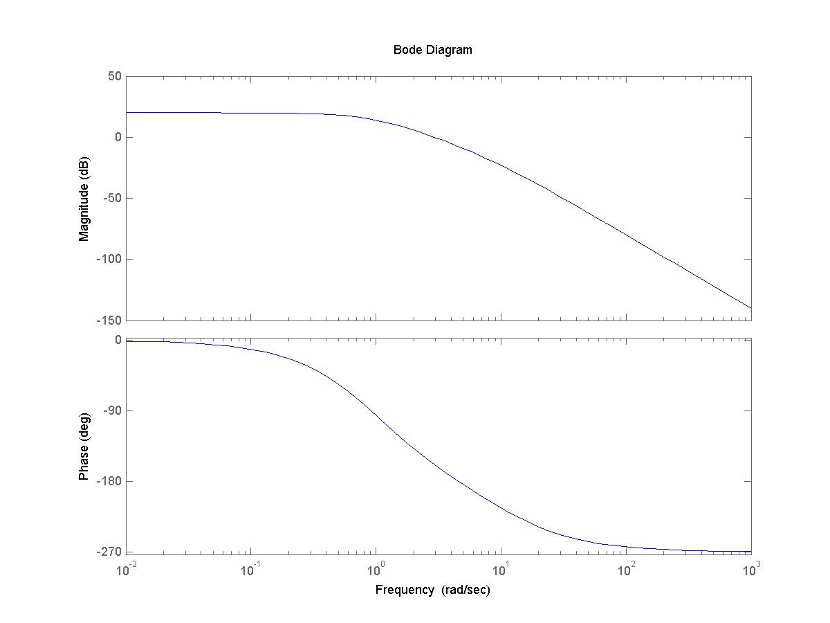
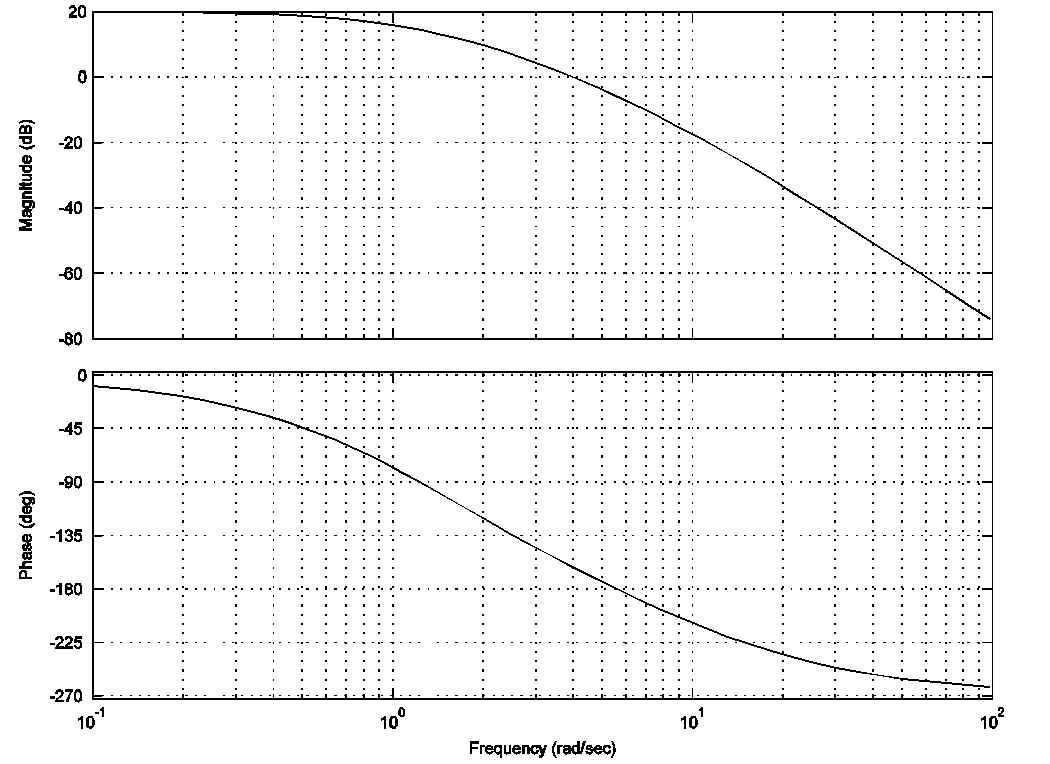
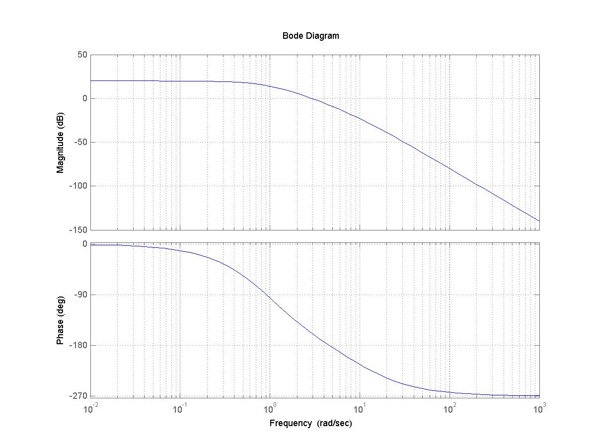
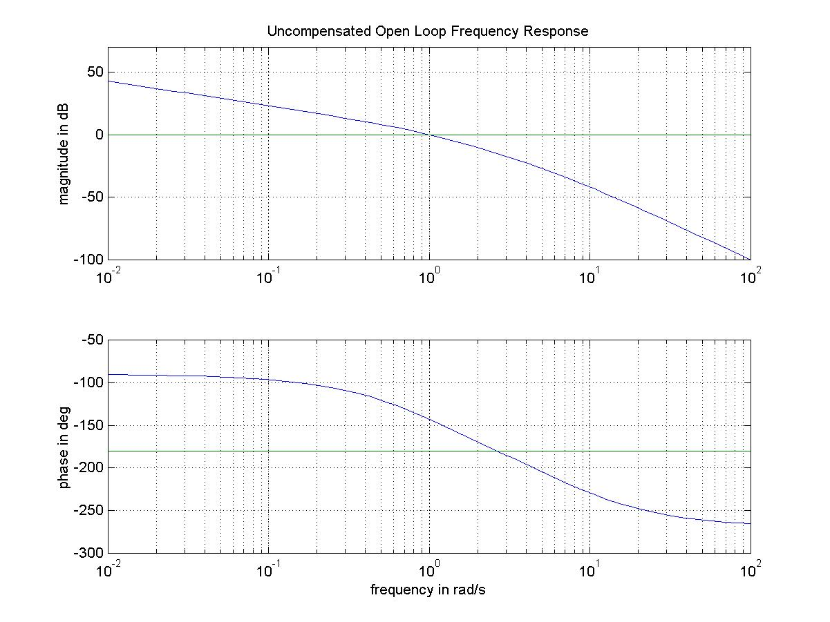
Consider a unit feedback system under dynamic control as shown. A Lead Controller will be implemented for this system. The open loop frequency response plot is provided.

Part 1. Specify conditions for the controller parameters [latex]a_1[/latex], [latex]a_0[/latex], [latex]b_1[/latex] so that it is a Lead Controller (as opposed to Lag Controller).
Part 2. Find the required controller DC gain [latex]a_0[/latex] so that the closed loop steady state error to a ramp input is 0.2 V/V.
Part 3. Adjust the magnitude scale on the Bode plot so that the plot reflects the frequency response for [latex]G_{open}(s)=a_0\cdot G(s)[/latex], with the value of the DC gain of the controller as found in item # 1. Determine the approximate phase crossover frequency and the phase margin of the adjusted system. Note that at this point the system is only under Proportional Control, as calculated in item # 1.
Part 4. The system is to be compensated with a Lead Controller. The requirements are: ramp error of no more than 0.2 V/V; closed loop system has a damping ratio of at least 0.3; Settling Time is to be less than 10 seconds. Design the Lead Controller to achieve the specifications outlined above. Show all the steps used to arrive at your answer.
13.7.6 Example
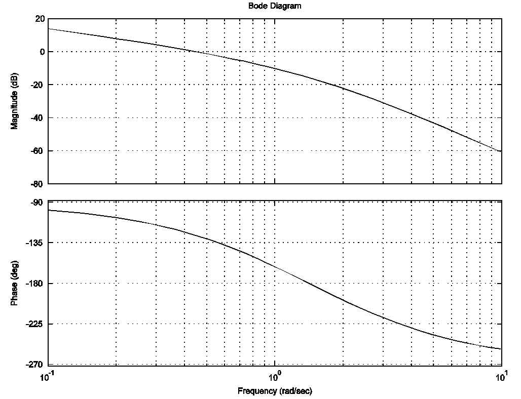
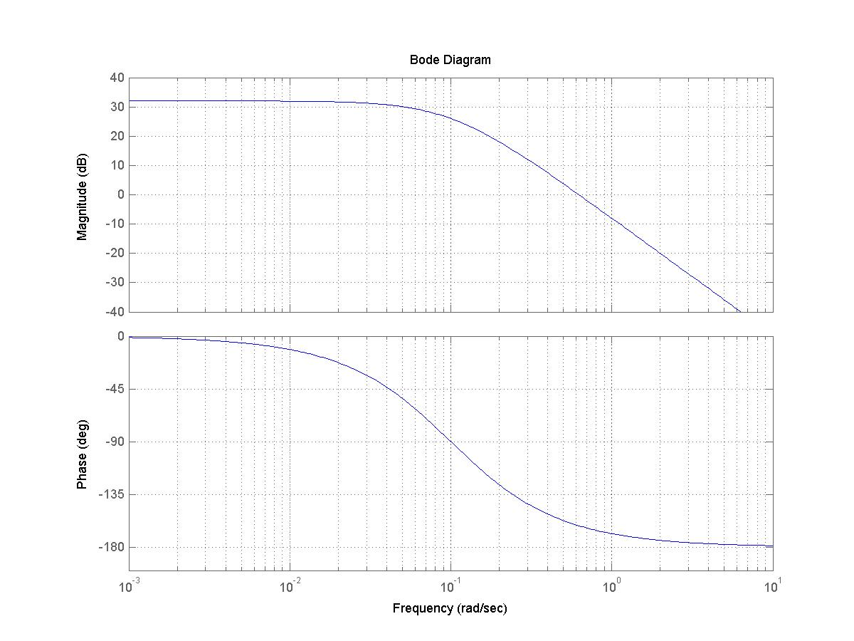
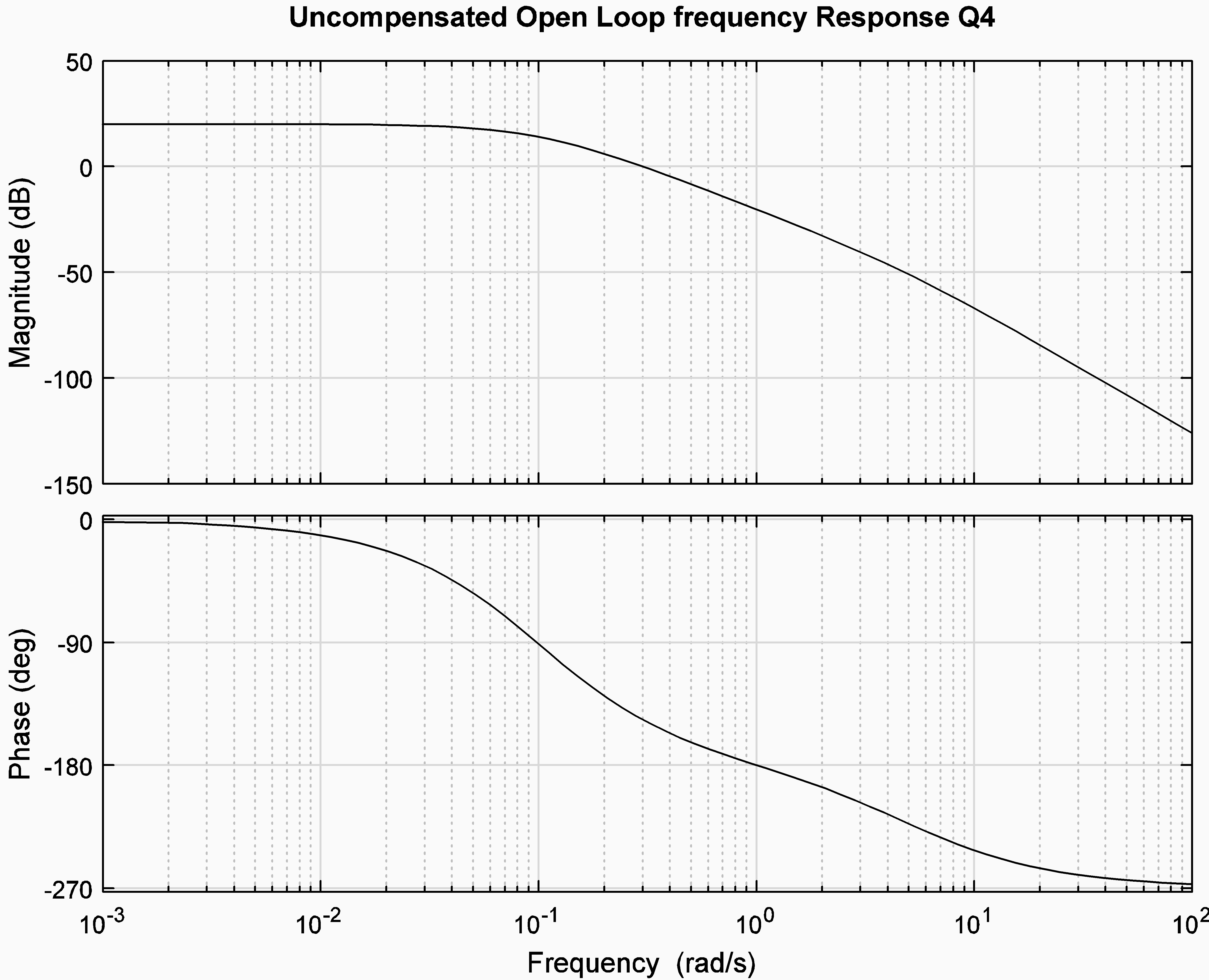
A unit feedback control system is shown, where the actuator/process transfer function is as shown below, K is a controller DC gain, and the LAG Controller structure is used. Frequency response plots of the process transfer function G(s) are shown as well.
[latex]G(s)=\frac{1}{s(s+1)(s+20)}[/latex]

[latex]G_c(s)=\frac{1+T\alpha}{1+Ts} [/latex], [latex]\alpha<1[/latex]
Part 1. Select a controller gain K and design a phase-lag compensator [latex]G_c (s)[/latex] such that the following requirements are met: a) the steady state error to a unit ramp input for the compensated closed loop system is less than 0.02, and b) the phase margin of the system is at least 45 degrees.
Write the controller transfer function, clearly specify all controller parameters ([latex]K, T, \alpha[/latex]), and superimpose the resulting compensated system plots on top of the plots. (Re-scale the axes if necessary.)
Part 2. Estimate the following specifications of the compensated closed loop unit step response: the percent overshoot; the settling time (provide your definition of the settling time); the steady state error to a unit ramp. Clearly show how you arrived at your estimates.

13.7.7 Example
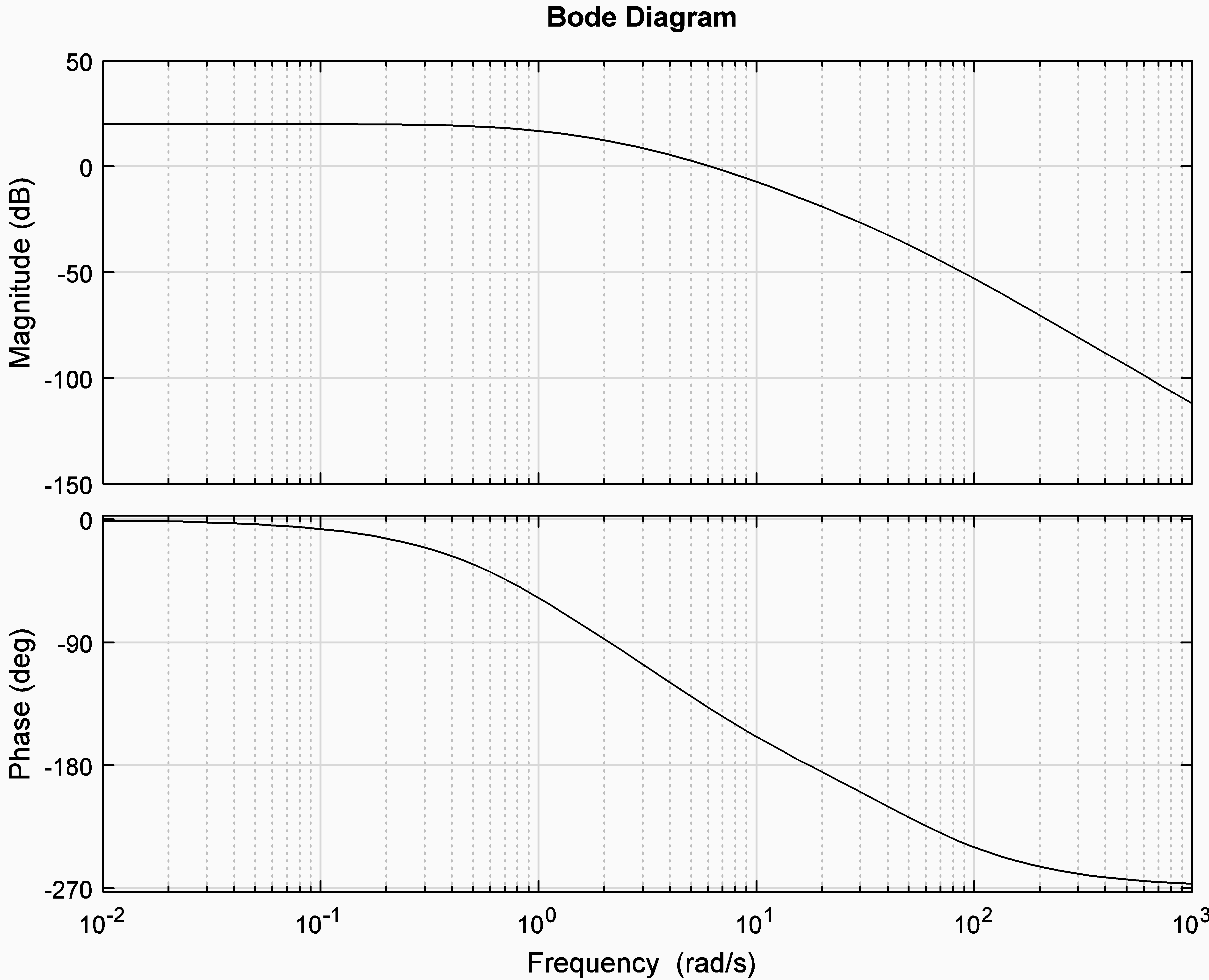
Consider a unit feedback control system. Frequency response plots of the process transfer function G(s) are as shown.
Part 1. Define the Second Order Model that would conform to these specifications. Read off the plot the current, uncompensated open loop frequency response parameters that affect the uncompensated closed loop step response: Position Constant, [latex]K_{pos}[/latex], Phase Margin, [latex]\Phi_m[/latex], and Crossover Frequency for Phase Margin, [latex]\omega_{cp}[/latex].
Part 2. Next, “translate” the requirements for the compensated closed loop step response into the desired compensated open loop frequency response parameters.
Part 3. Design a Lead Controller for this system. The compensated closed loop system is to have the following specifications for its unit step response: Percent Overshoot equal to 10%; Settling time (within [latex]\pm12\%[/latex] of the steady state value) equal to 1 second, and Steady state error (in %) equal to 1%.
Note that you do not need to know the transfer function of the system to design the required controller.
13.7.8 Example
Consider a unit feedback system under dynamic control, as shown below. Open loop Bode plot for the process is also included.
Part 1. A Lag Controller is to be implemented. Show what condition is to be met for the coefficients in the generic transfer function of the controller [latex]G_c(s)[/latex] in order for it to correspond to the LAG configuration (as opposed to the LEAD configuration):
[latex]G_c(s)=\frac{a_1s+a_0}{b_1s+1}[/latex]
Part 2. The system is to be compensated with a Lag Controller. The requirements are: step error of no more than 2%; closed loop system has a damping ratio of at least 0.45 – assume the Phase Margin [latex]\Phi_m = 45^{\circ}[/latex]; Phase crossover frequency is equal to [latex]\omega_{cp} = 3.0[/latex] rad/sec. Design the Lag Controller to achieve the specifications outlined above. Show all the steps used to arrive at your answer. Estimate selected step response specifications of the compensated closed loop system. As a first step, adjust the magnitude scale so that the plot reflects the frequency response for [latex]G_{open}(s) = a_0 \cdot G(s)[/latex], with the value of the DC gain of the controller as previously found. Determine the approximate phase crossover frequency and the phase margin of the adjusted system.
13.7.9 Example
An appropriate controller has to be designed for a unit feedback control system shown. The frequency response plots of the uncompensated open loop transfer function are included.

The compensated closed loop system response requirements are that the Percent Overshoot of the normalized unit step response be no more than 20% and that the steady state error in percent be no more than 5%. Try both the Lead and the Lag Controller design to meet the requirements.
13.7.10 Example
Consider a certain unit feedback closed loop system under proportional Control where the process is described by the following transfer function G(s), with the frequency response plots as shown.
[latex]G(s)=\frac{100}{{(s+1)}^2 (s+10)}[/latex]
Part 1. Estimate the following specifications of the uncompensated closed loop unit step response: Percent Overshoot PO, the settling time [latex]T_{settle(\pm2\%)}[/latex] and the steady state error [latex]e_{ss(step)\%}[/latex].
Part 2. The system is to be compensated by the Lag Controller with a transfer function as described:
[latex]G_c(s)=\frac{a_1 s + a_0}{b_1 s +1}[/latex], [latex]b_1 > \frac{a_1}{a_0}[/latex]
or
[latex]G_c(s)=K_{dc}\frac{\alpha\tau s +1}{\tau s +1}[/latex], [latex]\alpha <1 [/latex]
Design the Controller such that the following requirements are met: Steady State Error [latex]e_{ss(step)\%}[/latex] for the compensated closed loop system is less than 2%; Phase Margin [latex]\Phi_m[/latex] for the compensated system is equal to [latex]50^{\circ}[/latex];
Phase margin crossover frequency [latex]\omega_{cp}[/latex] is equal to 1 rad/sec. Clearly specify controller parameters in either of the forms shown and superimpose the compensated system plots on top of the provided uncompensated system Bode plots to illustrate your design.
Part 3. Estimate the following specifications of the compensated closed loop unit step response: Percent Overshoot PO, the settling time [latex]T_{settle(\pm2\%)}[/latex] and the steady state error [latex]e_{ss(step)\%}[/latex].
13.7.11 Example
A unity feedback control system is to operate under Lead Control, where the controller transfer function is:
[latex]G_c(s)=\frac{a_1 s+a_0}{b_1 s +1}=K_c\frac{1+\tau s}{1+\alpha\tau s}[/latex], [latex]0<\alpha<1[/latex]
Frequency response plots of the uncompensated open loop transfer function are shown.
Part 1. Estimate the following specifications of the uncompensated closed loop unit step response: the Percent Overshoot PO, the Settling Time [latex]T_{settle(\pm2\%)}[/latex] and the steady state error [latex]e_{ss(step)\%}[/latex], as well as the steady state error to a unit ramp [latex]e_{ss(ramp)}[/latex] . Clearly show how you arrived at your estimates.
Part 2. Design a phase Lead Compensator [latex]G_c(s)[/latex] such that the following requirements are met: the steady state error to a unit ramp input for the compensated closed loop system is less than or equal to 0.3([latex]e_{ss(ramp)} \leq 0.3[/latex] the percent overshoot is less than or equal to 15% [latex](PO \leq 15\%)[/latex]; the settling time is less than 3 sec [latex](T_{settle(\pm2\%)}\leq3)[/latex]. Write the controller transfer function, clearly specify all controller parameters [latex](K_c, \tau, \alpha)[/latex] and superimpose the resulting compensated system plots on top of the plots shown.
13.7.12 Example
A unit feedback control system is to operate under Lead Control, where the process transfer function is:
[latex]G(s)=\frac{0.5}{(s+5){(s+0.1)}^2}[/latex]
Frequency response plots for the uncompensated open loop system are shown next. Design requirements are: the Steady State Error for the unit step input for the compensated closed loop system is to be no more than 2%; Percent Overshoot of the compensated closed loop system is to be no more than 15%; the Settling Time, [latex]T_{settle(\pm2\%)}[/latex], is to be no more than 5 seconds.
PART A: Calculate the Position Constant for the uncompensated system [latex](K_{pos (uncomp)})[/latex], then the Position Constant for the compensated system [latex](K_{pos (comp)})[/latex] that would meet the design requirements. Read off the Phase Margin of the uncompensated system [latex](\Phi_{m(u)})[/latex] and then decide what value of the Phase Margin for the compensated system [latex](\Phi_{m(c)})[/latex] would meet the design requirements. Read off the Phase Margin crossover frequency of the uncompensated system [latex](\omega_{cp(u)})[/latex] and then decide what value of the crossover frequency for the compensated system [latex](\omega_{cp(c)})[/latex] would meet the design requirements. Calculate the appropriate Lead Controller parameters and the Controller transfer function. Show the general shape of the compensated frequency response by overlaying it on top of the uncompensated plot.
PART B: A Lead Controller was designed so that the compensated closed loop system met all the requirements. The closed loop transfer function of the closed loop system was derived as follows:
[latex]G_{cl_{comp}}=\frac{15.47s+2.45}{0.0489s^4+1.254s^3+5.25s^2+16.48a+2.5}[/latex]
[latex]=\frac{316.57(s+0.158)}{(s+21.37)(s+0.159)(s^2+4.134s+15.01)}[/latex]
Show that the steady state error, [latex]e_{ss(step)\%}[/latex], is indeed equal to 2%. Estimate the closed loop step response specs [latex]T_{settle(\pm2\%)}[/latex] and [latex]PO[/latex]. The actual values were: [latex]T_{settle(\pm2\%)}=1.5[/latex] seconds, and [latex]PO=15\%[/latex]. Explain any possible discrepancies between these values and the above estimates.
13.7.13 Example Lead Design – Winter 2017 Final Exam
Consider a unit feedback closed loop control system. The system is to operate under Lead Control. The process transfer function G(s) is as follows:
[latex]G(s)=\frac{2500}{(s+1)(s+5)(s+50)}[/latex]
Open loop frequency response plots of G(s) are as shown. Design requirements are: Steady State Error for the unit step input for the compensated closed loop system is to be no more than 4%. Percent Overshoot of the compensated closed loop system is to be no more than 20%. The Settling Time, [latex]T_{settle(\pm2\%)}[/latex], is to be no more than 0.5 seconds.
PART 1: Calculate the Position Constant for the uncompensated system [latex](K_{pos(u)})[/latex], then the Position Constant for the compensated system [latex](K_{pos(c)})[/latex] that would meet the design requirements.
PART 2: Read off the Phase Margin of the uncompensated system [latex](\Phi_{m(u)})[/latex] and then decide what value of the Phase Margin for the compensated system [latex](\Phi_{m(c)})[/latex] would meet the design requirements. Read off the crossover frequency of the uncompensated system [latex](\omega_{cp(u)})[/latex] and then decide what value of the crossover frequency for the compensated system [latex](\omega_{cp(c)})[/latex] would meet the design requirements.
PART 3: Calculate the appropriate Lag Controller parameters and clearly write the Lag Controller transfer function [latex]G_c(s)[/latex].
PART 4: Estimate the compensated closed loop step response specs: PO, [latex]e_{ss(step)\%}[/latex], [latex]T_{rise(0-100\%)}[/latex] and [latex]T_{settle(\pm2\%)}[/latex].
13.7.14 Example Lag Design – Winter 2018 Final Exam
Consider a unit feedback closed loop control system. The system is to operate under Lag Control. The process transfer function G(s) is as follows:
[latex]G(s)=\frac{1000(s+6)}{{(s+0.5)}^2(s+30)(s+40)}[/latex]
Open loop frequency response plots of G(s) are as shown. Design requirements are: Steady State Error for the unit step input for the compensated closed loop system is to be one-fifth of the Steady State Error for the uncompensated system. Percent Overshoot of the compensated closed loop system is to be no more than 15%.
PART 1: Calculate the Position Constant for the uncompensated system [latex](K_{pos(u)})[/latex], then the Position Constant for the compensated system [latex](K_{pos(c)})[/latex] that would meet the design requirements.
PART 2: Read off the Phase Margin of the uncompensated system [latex](\Phi_{m(u)})[/latex] and then decide what value of the Phase Margin for the compensated system [latex](\Phi_{m(c)})[/latex] would meet the design requirements. Read off the crossover frequency of the uncompensated system [latex](\omega_{cp(u)})[/latex] and then decide what value of the crossover frequency for the compensated system [latex](\omega_{cp(c)})[/latex] would meet the design requirements.
PART 3: Calculate the appropriate Lag Controller parameters and clearly write the Lag Controller transfer function [latex]G_c(s)[/latex].
PART 4: Estimate the compensated closed loop step response specs: PO, [latex]e_{ss(step)\%}[/latex], [latex]T_{rise(0-100\%)}[/latex] and [latex]T_{settle(\pm2\%)}[/latex].