Chapter 13
13.6 Lead-Lag Controller
Lead-Lag Control combines the benefits of both the Lead and the Lag Controllers. The transfer function of the Lead-Lag Controller is as follows:
| [latex]G_c(s) = K_c \cdot \frac{s\tau_1 +1}{s\alpha_1\tau_1+1}\cdot\frac{s\alpha_2\tau_s +1}{s\tau_2+1}[/latex] | Equation 13-27 |
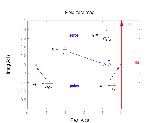
Kc corresponds to the DC gain of the controller and both [latex]\alpha_1 < 1[/latex], [latex]\alpha_2 <1[/latex]. There are two zeros, at [latex]s_1 = -\frac{1}{\tau_1}[/latex], and [latex]s_2 = -\frac{1}{\alpha_2\tau_2}[/latex], and two poles, at [latex]s_3 = -\frac{1}{\alpha_1\tau_1}[/latex] and [latex]s_4 = -\frac{1}{\tau_2}[/latex]. Note that what makes this compensator “tick,” is its sequence: POLE-ZERO-ZERO-POLE, as shown in Figure 13‑29. In the frequency domain, the four corner frequencies are:
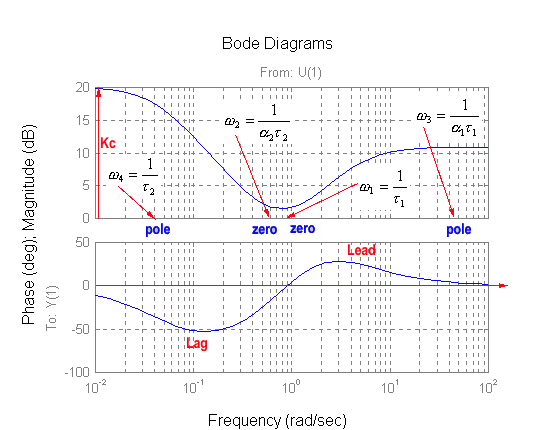
[latex]\omega_1 = \frac{1}{\tau_1}[/latex], [latex]\omega_2 = \frac{1}{\alpha_2\tau_2}[/latex], [latex]\omega_3 = \frac{1}{\alpha_1\tau_1}[/latex], [latex]\omega_4 = \frac{1}{\tau_2}[/latex]
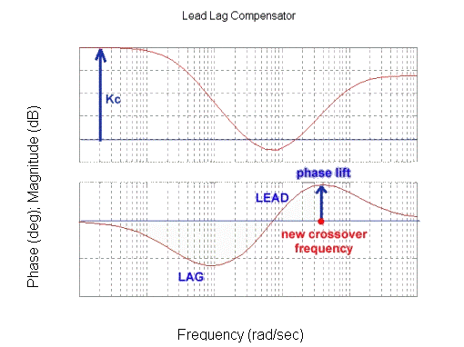
A frequency response plot of the lead-lag compensator is shown in Figure 13‑30. Again, note the sequence: POLE-ZERO-ZERO-POLE, as shown in Figure 13‑29. This structure is sometimes also referred to as the Lag-Lead Controller – the Lag block comes first on the frequency plot, followed by the Lead block as Figure 13‑30 shows. We will however use the name Lead-Lag Controller, based on the sequence in which its components are used in the design – the Lead component is used first, then the Lag component.


13.6.1 Simplified Lead-Lag Controller Design
Figure 13‑31 shows the values significant for the design procedure which is as follows: choose the compensator gain [latex]K_c[/latex], based on the steady state error requirements for the closed loop operation. Re-plot the open loop frequency response, including the required “gain lift”:
| [latex]G_{open}(j\omega)=K_cG(j\omega)H(j\omega)[/latex] | Equation 13-28 |
Assume the necessary phase margin [latex]\Phi_m[/latex], based on the required Percent Overshoot. Determine the crossover frequency [latex]\omega_{cp}[/latex], from the settling time requirement.
Determine the necessary phase lead lift [latex]\theta[/latex] at this frequency (add an extra 5 degrees, since the Lag Controller block will be used):
| [latex]\theta= \phi_{max} = -180^{\circ} + \Phi_m + 5^{\circ}-\angle GH(\omega_{cp})[/latex] | Equation 13-29 |

Calculate the Lead parameter [latex]\alpha_1[/latex]:
| [latex]\alpha_1 = \frac{1-\sin{\phi_{max}}}{1+\sin{\phi_{max}}}[/latex] | Equation 13-30 |
Calculate the Lead time constant [latex]\tau_1[/latex] from:
| [latex]\omega_{cp}=\omega_0=\frac{1}{\sqrt{\alpha_1}\tau_1}[/latex] | Equation 13-31 |
Calculate (or measure from the plot) the total open loop gain at the crossover frequency:
| [latex]M_{open}(j\omega_{cp})=\left | G(j\omega_{cp})H(j\omega_{cp}) \right | \cdot K_c\cdot\frac{1}{\sqrt{\alpha_1}}[/latex] | Equation 13-32 |
Calculate the Lag parameter [latex]\alpha_2[/latex] from a necessary gain reduction at this frequency:
| [latex]\alpha_2 = \frac{1}{M_{open}}[/latex] | Equation 13-33 |
Calculate the Lag time constant [latex]\tau_2[/latex] from:
| [latex]\omega_{cp}=\frac{10}{\alpha_2\tau_2}[/latex] | Equation 13-34 |
Comment:
This design theoretically meets all three typical performance requirements – accuracy, speed, and lack of oscillations. Whether it will work well, depends on how closely the compensated closed loop transfer function resembles our standard second order under-damped model, on which the design was based. Always run simulations of the closed loop system response under this compensation scheme – the design may require iterations to improve its performance.

