
Chapter 7
7.3 Examples
7.3.1 Example
Consider a certain closed loop control system as shown:

Find the closed loop system transfer function and determine the system parameters [latex]K_{dc}, \zeta,\omega_{o}[/latex]. Next, determine the following step response specifications: Percent Overshoot (PO), Settling Time ([latex]T_{settle(\pm 2\%)}[/latex]), Rise Time ([latex]T_{rise(10\% - 90\%)}[/latex]), period of oscillations ([latex]T_{period}[/latex]), and frequency of damped oscillations ([latex]\omega_{d}[/latex]), the System Type, Error Constants and Steady State Errors for the step, ramp and parabolic inputs.
7.3.2 Example
Consider a certain closed loop system operating under Proportional Control as shown, and find the gain value such that the system is stable and PO is approximately 20%. What is the Settling Time? Can it be improved?

7.3.3 Example
Consider a pole-zero map of a certain closed loop system, as shown. Estimate the settling time, [latex]T_{settle(2\%)}[/latex], of the system step response and the closed loop system damping ratio.

7.3.4 Example
Consider an unknown closed loop system with a normalized (i.e. scaled so that the reference input is equal to ) step response as shown. Find an appropriate model for the closed loop transfer function.

7.3.5 Example
Consider a response of a closed loop control system from Example 5.3.10. Read off transient and steady state step response specifications ([latex]PO, T_{rise(10\% - 90\%)} , T_{settle \pm 2\%}, T_{period},[/latex] and [latex]e_{ss\%}[/latex]). Based on the information, build an appropriate second order model for the system with such step response as shown.
7.3.6 Example
Consider a certain closed loop control system described by the following transfer function:
[latex]G_{cl}(s) = \frac{Y(s)}{R(s)} = \frac{22.5}{s^{2} + s + 25}[/latex]
Find the closed loop system damping ratio, frequency of natural oscillation and closed loop DC gain.
Next, estimate the following transient response specifications: percent overshoot (PO), settling time ([latex]T_{settle(\pm 2\%)}[/latex]), period ( [latex]T_{period}[/latex]), and frequency of damped oscillations (), as well as the following steady state specifications of this closed loop system: System Type as well as Position Constant, steady state error to a step input (in %), Velocity Constant, steady state error to a ramp input, Acceleration Constant and steady state error to a parabolic input.
How many cycles of oscillations will be visible in the system response? Justify your answer.
7.3.7 Example
Consider a response of a certain closed loop control system to a unit reference signal, shown in the figure below.
Read off appropriate values and/or calculate transient specifications (PO, settling time ([latex]T_{settle(\pm 2\%)}[/latex]), period ( [latex]T_{period}[/latex]) for this step response. Identify the System Type, Steady State Errors to unit step, ramp and parabolic inputs, as well as the corresponding Position, Velocity and Acceleration Constants. Based on the information read off in Part 1, create a second order model for the closed loop system with the response shown. Find the following system parameters: [latex]\zeta, \omega_{n}, K_{dc}[/latex] , as well as the complete model transfer function [latex]G_{model}(s)[/latex] .
7.3.8 Example
Consider a certain closed loop control system described by the following transfer function:
[latex]G_{cl}(s) = \frac{Y(s)}{R(s)} = \frac{80}{s^{2} + 5s + 100}[/latex]
Find the following model parameters: [latex]\zeta, \omega_{n}, K_{dc}[/latex]. Estimate transient response specifications (PO, settling time ([latex]T_{settle(\pm 2\%)}[/latex]), period ( [latex]T_{period}[/latex]) and steady state specifications of this closed loop system (System Type, [latex]K_{pos}, e_{ss(step)\%}, K_{v}, e_{ss(ramp)}, K_{a}, e_{ss(parab)}[/latex] ).
7.3.9 Example
Consider four separate second order systems, with the locations of their pole pairs shown. Answer the following questions and give brief justification to your answer.
Q: Which of the four systems exhibits the largest percent overshoot (PO) in its step response?
Q: Which of the four systems is unstable?
Q: Which of the four systems exhibits the shortest settling time in its step response?
Q: Which of the four systems has the highest frequency of oscillations in its step response?
Q: Which of the four systems exhibits the longest settling time in its step response?
Q: Which of the four systems exhibits the smallest percent overshoot (PO) in its step response?
Q: Which of the four systems has the smallest steady state error?
Q: What is the System Type?

7.3.10 Example
Consider closed loop responses of two different control systems (System A and System B), as shown. Match them to their appropriate pole locations also shown, briefly explain why.


7.3.11 Example
Consider a normalized step response of a certain LTI system, as shown. The reference is assumed to be a unit step.

Determine the Percent Overshoot (in %), Steady State Error (in %) and the Settling Time (within ±2% of the final value) for this response. Next, assume that this system can be modelled by a standard 2nd order model and calculate the appropriate parameters.
7.3.12 Example
Consider a response of a certain closed loop control system to a unit reference signal, shown in the figure below.

Read off appropriate values and/or calculate transient specifications (PO, settling time ([latex]T_{settle(\pm 2\%)}[/latex]), period ([latex]T_{period}[/latex]) for this step response. Based on the information read off in Part 1, create a second order model for the closed loop system with the response shown. Find the following system parameters: [latex]\zeta, \omega_{n}, K_{dc}[/latex], as well as the complete model transfer function [latex]G_{model}(s)[/latex]. Identify the System Type, Steady State Errors to unit step, ramp and parabolic inputs, as well as the corresponding Position, Velocity and Acceleration Constants.
7.3.13 Example
Consider a step response to a unit reference input of a control system as shown. Estimate the following specs: Percent Overshoot, Settling Time the Steady State Error. What are your estimates of the closed loop damping ratio [latex]\zeta[/latex], the frequency of natural oscillations [latex]\omega_{n}[/latex], and the DC gain?

7.3.14 Example
A step response of a certain control system is supposed to exhibit no more than 5% overshoot and to settle (use the 2% definition of the settling time) within (2) seconds. Show a shaded area in the S-Plane where the dominant closed loop poles of the system should be located so that both conditions are met.
7.3.15 Example
Consider the closed loop control system as shown here.

For [latex]\tau = = 2[/latex] seconds, the desired closed loop ratio is to be [latex]\zeta = \frac{1}{\sqrt{2}}[/latex]. Find the corresponding Controller gain K and the resulting settling time of the closed loop step response. Next, assume that the desired closed loop ratio is still to be [latex]\zeta = \frac{1}{\sqrt{2}}[/latex]. but we would like to shorten the settling time to [latex]T_{settle \pm 2\%} = 2[/latex] seconds. If the time constant is variable, what value would it have to be? For that case, find the corresponding Controller gain K.
The closed loop system characteristic equation Q(s) is a quadratic, resulting in TWO closed loop poles:
[latex]Q(s) = 0[/latex] [latex]s^{2} + \frac{1}{\tau}s + \frac{K}{\tau} = 0[/latex]
Assume that K = 0.25 and [latex]\tau[/latex]is a variable:
[latex]s^{2} + \frac{1}{\tau}s + \frac{0.25}{\tau} = 0[/latex] [latex]\rightarrow[/latex] [latex]\tau s^{2} + s + 0.25 = 0[/latex]
Find analytical expressions for both poles [latex]p_{1}, p_{2}[/latex] as a function of [latex]\tau[/latex].
7.3.16 Example
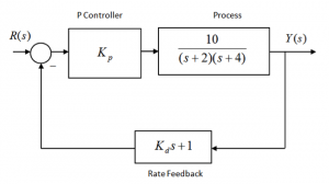
Consider two closed loop systems as shown in the first block diagram:
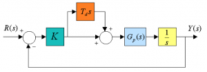
The process transfer function [latex]G_{p}(s)[/latex] is given by:
[latex]G_{p}(s) = \frac{1}{s+p}[/latex]
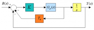
Show that the closed loop system of the first system is of a second order. Find the range of gains for closed loop stability, the critical gain and the frequency of resulting marginally stable oscillations. Next, reconfigure the controller as shown in the second block diagram and show that both closed loop systems have the same characteristic equation.
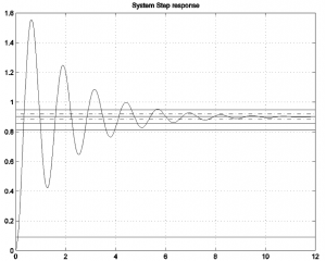
Suppose that a choice of K is made so that both of the closed loop systems are stable. The graph shown next illustrates their step responses for this choice of K. Identify which step response corresponds to which configuration. Briefly justify your answer.

7.3.17 Example
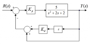
Consider again the system from Example 5.3.9, describing a certain system under Proportional + Rate Feedback Control. Find the closed loop system transfer function in terms of controller gains [latex]K_{p}[/latex] and [latex]K_{d}[/latex] and determine values of the controller gains such that PO = 10% and Settling time (within [latex]\pm2\%[/latex]) = 1 second. Write out the closed loop transfer function of the system for these values of the controller gains.
7.3.18 Example
Consider a certain process described by the following transfer function:
[latex]G_{op}(s) = \frac{200}{s^{s} + 5s + 49}[/latex]
Find the specifications of a closed loop system without any controller. Next, assume Proportional Control and find the controller gain such that the closed loop response has a steady state error no larger than 4%. Finally, add the rate feedback to the controller scheme and find an appropriate Derivative gain such that the Percent Overshoot is no more than 15%. Estimate what the resulting settling time would then be.
7.3.19 Example
Let’s continue with the previous example. Assume that we have the same process transfer function that the closed loop system will have the Rate Feedback, as well as Proportional Controller scheme. We would like to have the Percent Overshoot equal to 15%, and the settling time (2% criterion) equal to 0.1 seconds. Find appropriate values for both Controller gains, and estimate the resulting steady state error.
7.3.20 Example
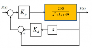
Consider the block diagram below, describing a certain control system where a Proportional + Rate Feedback control is implemented with two gains [latex]K_{p}[/latex] and [latex]K_{d}[/latex] .
Find a closed loop system transfer function in terms of controller gains, [latex]K_{p}[/latex] and [latex]K_{d}[/latex]. Next, find the values of gains [latex]K_{p}[/latex] and [latex]K_{d}[/latex]. such that the resulting Percent Overshoot of the closed loop step response will be equal to 15% and the settling time, [latex]T_{settle\pm2\%}[/latex], will be equal to 1.5 seconds. What is the closed loop transfer function expression for the computed values of controller gains? For the computed values of controller gains, find the closed loop system DC gain [latex]K_{dc}[/latex], and the closed loop steady state error for the step response, [latex]e_{ss(step)\%}[/latex].
7.3.21 Example
Consider the block diagram below, describing a control system where the Proportional + Rate Feedback control is implemented with two control parameters, K and [latex]T_{d}[/latex] and an inner feedback loop. Note that traditionally, to denote a Rate (as well as a Derivative) Gain, two names are interchangeably used – Rate (or Derivative) Gain, and Rate (or Derivative) Time Constant, which is the inverse of the Gain. Note as well that this is a slightly different P + Rate Feedback arrangement of components than the one in Example 7.3.20 (i.e. the inner feedback loop).
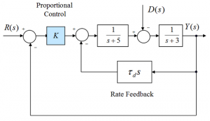
First, find both closed loop system transfer functions in terms of controller parameters [latex]K, T_{d}[/latex]. Next, assume the Disturbance signal to be zero and find their values such that the steady state error of the system step response, [latex]e_{ss(step)\%}[/latex], is equal to 10%, and the closed loop damping ratio [latex]\zeta[/latex]equal to 0.7. For the calculated values of controller parameters, estimate the resulting settling time of the step response, [latex]T_{settle\pm 2\%}[/latex].
Next, assume that [latex]r(t) = 1(t)[/latex] and [latex]d(t) = 0.5 \cdot 1(t)[/latex] where 1(t) is a unit step function. If K and [latex]T_{d}[/latex] are as calculated above, what is the steady state value of the output signal? What will the steady state error be? Repeat for [latex]r(t) = 1(t)[/latex] and [latex]d(t) = 10 \cdot 1(t)[/latex] What needs to be done to reduce the effect of the disturbance on the system response? Explain briefly.
7.3.22 Example
A feedback control system with positive controller gains [latex]K_{1}[/latex] and [latex]K_{2}[/latex] is configured as follows:
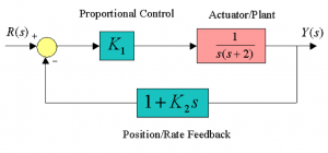
Find an expression for [latex]K_{2}[/latex] in terms of [latex]K_{1}[/latex] in terms of so that the steady state error to a ramp ( [latex]r(t) = t, t \geq 0[/latex] ), is less than 1 unit. Sketch the desired locations of the closed loop system poles in the complex plane in order to achieve the following performance specifications:
- The damping ratio of the poles [latex]\zeta \geq 0.707[/latex]
- The settling time [latex]T_{settle \pm2\%} \geq 3[/latex] seconds.
Set the rate feedback gain [latex]K_{2} = 0.1[/latex] and find the minimum value of the proportional gain [latex]K_{1}[/latex] so that all of the performance specifications listed in Parts 1 and 2 can be achieved.
7.3.23 Example
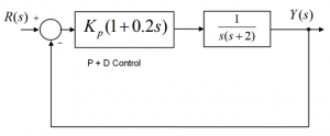
Consider a closed loop position control system working under Proportional + Rate Feedback Control, as shown.
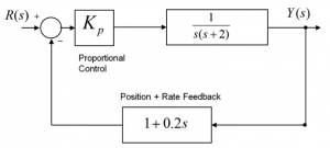
Determine the Proportional Gain value [latex]K_{p}[/latex] such that the following performance specifications can be achieved: the damping ratio of the poles [latex]\zeta \geq 0.707[/latex] and the settling time [latex]T_{settle \pm2\%} \geq 3[/latex] seconds. For the value of as found above, estimate the following closed loop specifications: [latex]PO, T_{rise(10\% - 90\%)}, T_{settle \pm2\%} , T_{period}[/latex] . Also, determine the System Type, Error Constants and Steady State Errors.
Part 3. If the Proportional + Rate Feedback Control is replaced by the Proportional + Derivative Control, how would the response specifications under P + D Control change, compared to your calculations in Part 2 for Proportional + Rate Feedback?
7.3.24 Example
Consider a closed loop control system working under a Proportional + Rate Feedback Control, as shown below:
Find the controller gains [latex]K_{p}, K_{d}[/latex]such that the closed loop system will meet the following conditions:
- The closed loop operation is stable;
- The steady state error, in %, for a normalized step input, is equal to 5%;
- The closed loop step response has PO = 5%.
With the controller gain values as calculated, what will be the step response Settling Time (within 2%)?
7.3.25 Example
Consider the same block diagram, shown below, as in Example 2.6.11, of the servo-control system for a position control of one of the joints of a robot arm, operating under Proportional Control. Let’s assume a simplified model for this system, shown below, where the armature inductance L = 0 H. All other parameters remain the same as in Example 2.6.11.
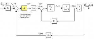
Find the closed loop transfer function between reference [latex]\omega_{ref}[/latex] angle and the load position angle [latex]\omega_{load}[/latex] for the simplified model of the system:
[latex]G_{m}(s) = \frac{\omega_{load}(s)}{\omega_{ref}(s)}[/latex]
Next, find the value of the controller gain such that the closed loop system has the damping ratio [latex]\zeta \geq 0.707[/latex] of. For this value of the controller gain, estimate Percent Overshoot, PO, of the system unit step response, Steady State Error [latex]e_{ss(step)\%}[/latex], and Settling Time, [latex]T_{settle\pm 2\%}[/latex].
