Chapter 2
2.2 Locations in s-Plane vs. Time Response
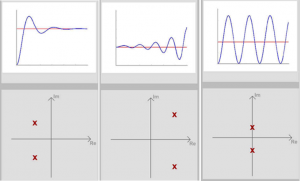
Figure 2‑1 below shows three possible s-Plane locations for a pair of complex conjugate poles. Recall that the pair of complex conjugate poles results in oscillatory time response, where the Real part of the pole determines the decay rate of the response, while the Imaginary part of the pole determines the frequency of oscillations.

The first panel of Figure 2‑1 illustrates a stable response, the second panel illustrates an unstable response, and the third panel illustrates a marginally stable response. The system’s respective behaviours will be labelled as “Stable”, “Unstable” and “Marginally Stable”. Because we have the pair of complex conjugate poles, the second, “Unstable”, case results in an oscillatory instability.
Note that these three behaviours can also be applied to a case where the system pole(s) are real. Real poles result in transient(s) of exponential form. When [latex]Re\{p_{i}\} < 0[/latex] we will have a combination of exponential decays, when [latex]Re\{p_{i}\} = 0[/latex] we will have a constant (step) response, and when [latex]Re\{p_{i}\} > 0[/latex], we will have an exponentially increasing (but of single polarity, not oscillating) unstable response. Thus this case is referred to as monotonic instability. Refer to Online Tutorials for more on System Stability.

