
Chapter 5
5.3 Examples
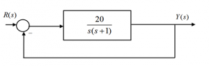
5.3.1 Example
Consider a unit feedback control system under Proportional Control as shown:
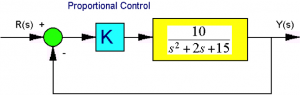
Find the closed loop system type, error constants and errors.
5.3.2 Example
Consider a unit feedback control system under Proportional Control as shown:
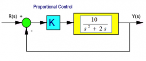
Find the closed loop system type, error constants and errors.
5.3.3 Example
Consider a unit feedback control system under Proportional Control as shown:
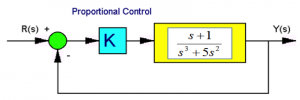
Find the closed loop system type, error constants and errors.
5.3.4 Example
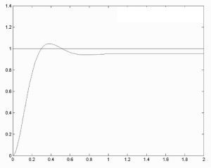
Consider a plot showing a closed loop response of a certain control system in a closed loop configuration to a normalized unit reference input. What is the System Type, N?
5.3.5 Example
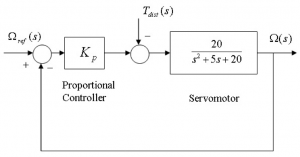
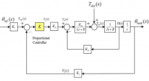
Consider the rotational positioning control system as shown, subject to a torque disturbance, [latex]T_{dist}(s)[/latex] and with a reference position signal, [latex]\Omega_{ref}(s)[/latex]. Using normalized units, assume a unit reference signal and the disturbance of a 0.2 magnitude. What condition would the Proportional Gain [latex]K_{p}[/latex] have to meet in order to maintain the steady state error of the system response to be less than 10%?
5.3.6 Example
Consider again the system under Proportional Control, as shown in Example 2.6.4. Find the range of operational gains such that the system is stable AND the steady state error to the unit step reference signal is less than 10%. When the error is exactly 10%, what is the system Gain Margin? Is it possible to operate the closed loop system that the steady state error requirement is no more than 5%?
5.3.7 Example
Consider again the block diagram from Example 2.6.3. What is the System Type? Determine the system error constants and the corresponding closed loop system errors when the system tracks a unit step reference signal, a unit ramp reference signal and a unit parabolic reference signal.
Next, find the range of operational gains such that the system is stable AND the steady state error to the unit step reference signal is less than 10%. When the error is exactly 10%, what is the system Gain Margin? Is it possible to operate the closed loop system that the steady state error requirement is no more than 5%? If yes, why? If no, why?
5.3.8 Example
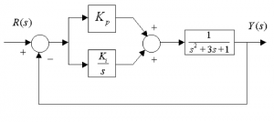
Consider the following block diagram describing a system under Proportional-Integral control (PI):
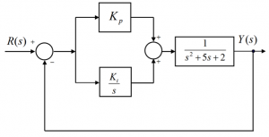
Part 1. Find the system closed loop transfer function, [latex]G_{cl}(s)[/latex], in terms of the controller gains [latex]K_{p}[/latex] and [latex]K_{i}[/latex].
Part 2. Determine the System Type, and calculate the position, velocity and acceleration constants [latex]K_{pos}, K_{v}, K_{a}[/latex] and the corresponding steady state errors to unit step, ramp and parabolic input signals, all in terms of the controller gains [latex]K_{p}[/latex] and [latex]K_{i}[/latex].
Part 3. Use the Routh-Hurwitz criterion to obtain an expression for gain [latex]K_{p}[/latex] in terms of gain [latex]K_{i}[/latex] so that the closed loop stability is achieved.
Part 4. Find the minimum values of [latex]K_{p}[/latex] and [latex]K_{i}[/latex] such that the closed loop stability is achieved and the steady state error to an input signal [latex]r(t) = 3 + 2t, t \geq 0[/latex] is less than or equal to 0.1 V/V.
5.3.9 Example
Consider the following block diagram describing a system under Proportional + Rate Feedback Control:
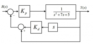
Determine the system type, error constants and errors in terms of the system controller gains. Next, assume the steady state error for the closed loop response is supposed to be 10%. What should be the value of the Proportional Gain?
5.3.10 Example
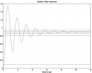
Consider a response of a certain closed loop control system to a unit reference signal, shown in the figure below. Read off appropriate values and/or calculate transient specifications ([latex]PO, T_{rise(10\%-90\%)},T_{settle \pm 2\%}, T_{period}[/latex]) and identify system type, errors and error constants.
5.3.11 Example
An actuator/process in a unit feedback closed loop configuration has the following transfer function:
Part 1. Determine the system type number, and calculate the system error constants [latex]K_{pos}, K_{v}[/latex] and [latex]K_{a}[/latex] .
Part 2. Find the steady state error to an input signal [latex]r(t)[/latex], where [latex]r(t) = 3t + e^{-t}, t \geq 0[/latex].
5.3.12 Example
Consider the following block diagram describing a system under Proportional-Integral control (PI):
Find the system open loop transfer function, [latex]G_{open}(s)[/latex]. Determine the system type number, and compute the position, velocity and acceleration constants [latex]K_{pos}, K_{v}, K_{a}[/latex], and the corresponding steady state errors to unit step, ramp and parabolic input signals. Use the Routh-Hurwitz criterion to obtain an expression for gain [latex]K_{p}[/latex] in terms of gain [latex]K_{i}[/latex] so so that the closed loop stability is achieved. Find the minimum values of [latex]K_{p}[/latex] and [latex]K_{i}[/latex] such that the marginal closed loop stability is achieved and the steady state error to an input signal [latex]r(t) = 3+2t, t \geq 0[/latex] is less than or equal to 0.1. Compute the resulting closed loop system pole locations.
5.3.13 Example
Let us re-visit the feedback system from Example 3.3.15, where we found the system transfer function using Mason’s Gain Formula. Let us consider continuing with this question – given the unit reference, calculate the smallest gain [latex]K_{1}[/latex] that can be used if the steady state error to a step load disturbance d(t) is to be less than 1%. Calculate the Gain Margin of the system at this value of gain [latex]K_{1}[/latex]. Is the system stable?
5.3.14 Example
Let us re-visit the feedback system from Example 3.3.19. Recall that we determined the stability conditions for this example. Next, consider the error requirements. The step response of the closed loop system should have a steady state error of less than 5%, and the unit ramp response should have a steady state error of 0.15 V/V; Find the required Controller gains, [latex]K_{p}[/latex] and [latex]K_{i}[/latex], to meet these conditions. Will the closed loop system be stable at these values?
5.3.15 Example
Let us re-visit the feedback system from Examples 2.6.11 and Example 3.3.12. Show why it is not possible to operate the system so that the Steady State Error for a [latex]45^{\circ}[/latex] step input is [latex]e_{ss(step)\%} = 1\%[/latex]. CAUTION: [latex]45^{\circ}[/latex] Input is NOT in S.I. units! Next, find the Controller gain such that the Steady State Error for a [latex]45^{\circ}[/latex] step input is.
5.3.16 Example
Let us re-visit the feedback system from Examples 2.6.11, 3.3.12 and 5.3.15, but consider now that the disturbance signal is positive, as shown below. Let’s also change the values of the system parameters, and of the inputs – the system’s parameters are as follows: [latex]K_{t} = 0.1\frac{v. sec}{rad}[/latex], [latex]K_{a} = 50\frac{V}{V}[/latex] – amplifier gain, [latex]K_{m} = 1.5\frac{N. m}{A}[/latex] – motor torque constant, [latex]R = 2 \Omega[/latex] – armature resistance, [latex]L = 0.1H[/latex] – armature inductance, [latex]K_{b} = 1.5\frac{V. sec}{rad}[/latex] – CEMF constant, [latex]J = 0.5\frac{N. m \cdot sec^{2}}{rad}[/latex] – motor & load inertia, and [latex]B = 0.7\frac{N. m. sec}{rad}[/latex] – motor & load linear friction coefficient, [latex]\theta_{ref_ss} = 50^{\circ}[/latex], [latex]T_{disst_ss} = 0.5 N. m[/latex].
Show why it is not possible to operate the system so that the Steady State Error for a [latex]50^0[/latex] step input is [latex]e_{ss(step)\%} = \pm 1\%[/latex]. Next, find if it is possible that the Steady State Error for a step input is [latex]50^{\circ}[/latex] step input is [latex]e_{ss(step)\%} = \pm 2\%[/latex].
5.3.17 Example
Let us re-visit the feedback system from Examples 2.6.11, 3.3.12, 5.3.15 and 5.3.16, but consider now the system without the disturbance signal, as shown below. Let’s also change the values of the system parameters, as follows:
[latex]K_{t} = 0.1\frac{v}{rad}[/latex], [latex]K_{a} = 30\frac{V}{V},K_{m} = 1.5\frac{N. m}{A}[/latex], [latex]R = 2 \Omega, L = 0.1H[/latex],[latex]K_{b} = 1.5\frac{V.sec}{rad},J = 0.5\frac{N. m . sec^{2}}{rad}[/latex], and [latex]B = 0.4\frac{N. m. sec}{rad}[/latex]. Determine if it is possible to operate the system at such Proportional Gain value, [latex]K_{op}[/latex], that the Gain Margin, [latex]G_{m}[/latex], is equal to 2 V/V, and the Steady State Error for the unit ramp input, [latex]e_{ss(ramp)}[/latex], is equal to 0.1 V/V.
5.3.18 Example
Let us re-visit the feedback system from Example 3.3.19. In it, we derived the transfer function of the robotic arm under the Proportional + Integral (PI) Controller, where the input was the reference angular velocity (speed) for the robot arm, the output is the actual load velocity of the arm. The transfer function was as follows:
[latex]G_{cl}(s) = \frac{15(K_{p}s + K_{i})}{s^{3} + 20s^{2} + (84 + 15K_{p})s + 15K_{i}}[/latex]
We also investigated the system stability, and found the practical condition to be that both controller gains have to be positive ([latex]K_{i} > 0[/latex] and [latex]K_{p} > 0[/latex]) – see solution to Example 3.3.19 for details. Now let us consider the following questions. The unit step response of the closed loop system should have a steady state error of less than 5%, and the unit ramp response should have a steady state error of 0.15 V/V. Find the required Controller gains, [latex]K_{i}[/latex] and [latex]K_{p}[/latex] , to meet these conditions. Will the closed loop system be stable at these values?
Next, assume that the operating Controller gains are: [latex]K_{i} = 18, K_{p} = 3[/latex] Find the expression for a unit step response of this system, [latex]\theta(t), t \geq 0[/latex]. HINT: one of the closed loop poles is at – 5.
5.3.19 Example
Let us re-visit the feedback system from Example 3.3.21. In it, we derived the transfer function of the robotic arm under the Proportional + Integral (PI) Controller, where the input was the reference angular velocity (speed) for the robot arm, the output is the actual load velocity of the arm. The transfer function was as follows:
[latex]G_{cl}(s) = \frac{18(K_{p}s + K_{p})}{s^{2} + (20 + 18K_{cl})s + (84 + 18K_{p})s} \cdot \frac{1}{s}[/latex]
We also investigated the system stability, and found the practical condition to be that both controller gains have to be positive ([latex]K_{i} > 0[/latex] and [latex]K_{p} > 0[/latex]) – see solution to Example 3.3.19 for details. Now let us consider the following questions. The unit step response of the closed loop system should have a steady state error of less than 5%, and the unit ramp response should have a steady state error of 0.15 V/V. Find the required Controller gains, [latex]K_{i}[/latex] and [latex]K_{p}[/latex] , to meet these conditions. Will the closed loop system be stable at these values?
Next, assume that the operating Controller gains are: [latex]K_{p} = 15, K_{cl} = 2.5[/latex] Find the expression for a unit step response of this system, [latex]\theta(t), t \geq 0[/latex]. HINT: one of the closed loop poles is at – 9.
5.3.20 Example
Let us re-visit the feedback system from Example 3.3.22. In it, we derived the transfer function of the robotic arm under the Proportional + Integral (PI) Controller, where the input was the reference angular velocity (speed) for the robot arm, the output is the actual load velocity of the arm. The transfer function was as follows:
[latex]G_{cl}(s) = \frac{18(K_{p}s + K_{p})}{s^{3} + 20s^{2} + (84 + 18K_{cl})s + 18K_{p})}[/latex]
We also investigated the system stability, and found the practical condition to be that both controller gains have to be positive ([latex]K_{i} > 0[/latex] and [latex]K_{p} > 0[/latex]) – see solution to Example 3.3.19 for details. Now let us consider the following questions. The unit step response of the closed loop system should have a steady state error of less than 5%, and the unit ramp response should have a steady state error of 0.15 V/V. Find the required Controller gains, [latex]K_{i}[/latex] and [latex]K_{p}[/latex] , to meet these conditions. Will the closed loop system be stable at these values?
Next, assume that the operating Controller gains are: [latex]K_{p} = 15, K_{cl} = 2.5[/latex]Find the expression for a unit step response of this system, [latex]\theta(t), t \geq 0[/latex]. HINT: one of the closed loop poles is at – 9.
5.3.21 Example
Let us re-visit the feedback system from Example 2.6.14. In it, we derived the closed loop transfer function of the system under the Proportional Control. The transfer function was found to be as follows:
[latex]G_{closed}(s) = \frac{K_{p} \cdot (s^{2} + 20s + 100)}{s^{3} + (3 + K_{p})s^{2} + (3 + 20K_{p})s} + (1 + 100K_{p})[/latex]
Find the required Controller gain ([latex]K_{p}[/latex]) so that all three of the following conditions are met:
- Stable operation with a positive Proportional Gain;
- Steady State Error for step input: [latex]e_{ss(step)\%} \leq 1\%[/latex];
- Gain Margin: [latex]G_{m}= 5\frac{V}{V}[/latex].
