Chapter 6
6.1 First order systems
A first order system is described by the transfer function in Equation 6‑1:
| [latex]G(s) = \frac{K}{s+a} = \frac{K_{dc}}{s\tau + 1}[/latex] |
Equation 6‑1 |
[latex]G(s)[/latex] has only one pole, and no zeros. Its unit step response can be derived as shown in Equation 6‑2:
|
[latex]Y(s) = \frac{1}{s}G(s) = \frac{K}{s(s+a)} = \frac{K_{1}}{s} + \frac{K_{2}}{(s+a)}[/latex] [latex]K_1=\left .\begin{matrix} \frac{K}{s} \end{matrix}\right|_{s=0}=\frac{K}{a}[/latex] [latex]K_2=\left .\begin{matrix} \frac{K}{s+a} \end{matrix}\right|_{s=-a}=\frac{-K}{a}[/latex] [latex]Y(s) = \frac{K}{a}. \frac{1}{s} - \frac{K}{a}. \frac{1}{(s+a)}[/latex] [latex]y(t) = \frac{K}{a}. (1-e^{-at}. 1(t) = K_{dc}\left ( 1-e^{1\frac{t}{\tau}} \right ). 1(t)[/latex] |
Equation 6‑2 |
Note that:
|
[latex]\frac{dy}{dt} = \frac{K_{dc}}{\tau}e^{-\frac{t}{\tau}}. 1(t)[/latex] [latex]\frac{dy}{dt} (0)= \frac{K_{dc}}{\tau} \neq 0[/latex] |
Equation 6‑3 |
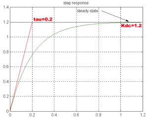
If the unit step input is used, the process DC gain and time constant can be evaluated directly from the graph, as shown in the following example.
6.1.1 Example
Consider a plot of the response of a certain unknown process, shown in Figure 6‑1. We would like to derive a model for this unknown system, i.e. a transfer function that would give a response closest to that of our system, let’s call it [latex]G_{m}(s)[/latex]. The response looks like an exponential rise with a non-zero slope at t=0 and is therefore identified as the response of a first order process (system). As such, the response can be described by the following equation:
[latex]y(t) = K_{dc}(1-e^{-\frac{t}{\tau}}). 1(t)[/latex]


