
Chapter 9
9.4 Proportional + Integral Control
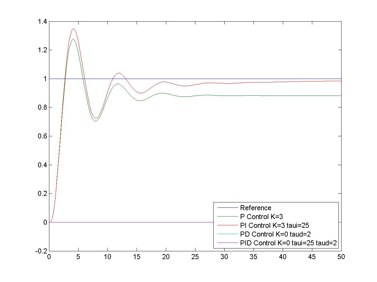
Let’s consider again the example from Chapter 9.2, where G(s) was described by Equation 9‑3. Assume the closed loop system has a PI Control implemented. You are, or will be, be familiar with the PI Control from Lab 3. Replace the Proportional Controller in Figure 9‑9 with the PI Controller described by the following transfer function:
| [latex]G_{PI}(s)=K_p\cdot \left ( \frac{K_i}{s}+1 \right )[/latex] or | |
| [latex]G_{PI}(s)=K_p\cdot \left ( \frac{1}{\tau_i s}+1 \right )[/latex] | Equation 9-8 |
The adjustable integral variable in the PI Controller is represented either by the Integral Gain, [latex]K_i[/latex], or the Integral Time Constant, [latex]\tau_i[/latex]. Note that [latex]\tau_i =\frac{1}{K_i}[/latex] The closed loop system transfer function is then as follows:
| [latex]G_{clPI}(s)=\frac{K_p\left(1+\frac{K_i}{s} \right )G(s)}{1+K_p\left(1+\frac{K_i}{s} \right )G(s)} = \frac{10K_p (s + K_i)}{s^5+15s^4+54s^3+30s^2+(4+10K_p)s+10K_p K_i}[/latex] | Equation 9-9 |
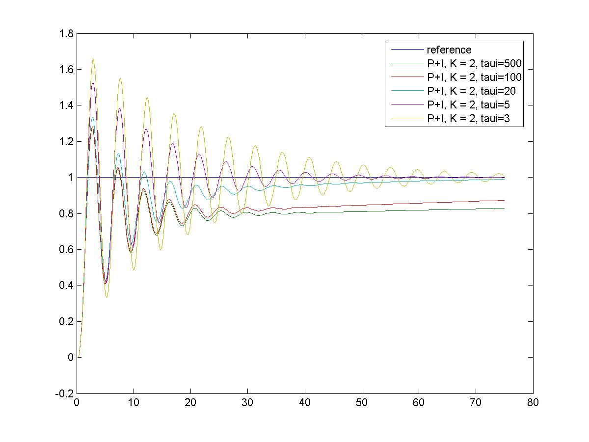
We can use either the expression for Integral Gain or its inverse, called the Integral Time Constant. Let’s have [latex]\tau_i = 5[/latex] seconds. The critical gain (for marginal stability of the closed loop) can be calculated from the Routh-Hurwitz Criterion as [latex]K_{crit} = 6.65[/latex] and the resulting frequency of marginal oscillations is calculated as [latex]\omega_{osc} = 1.17[/latex] rad/sec.
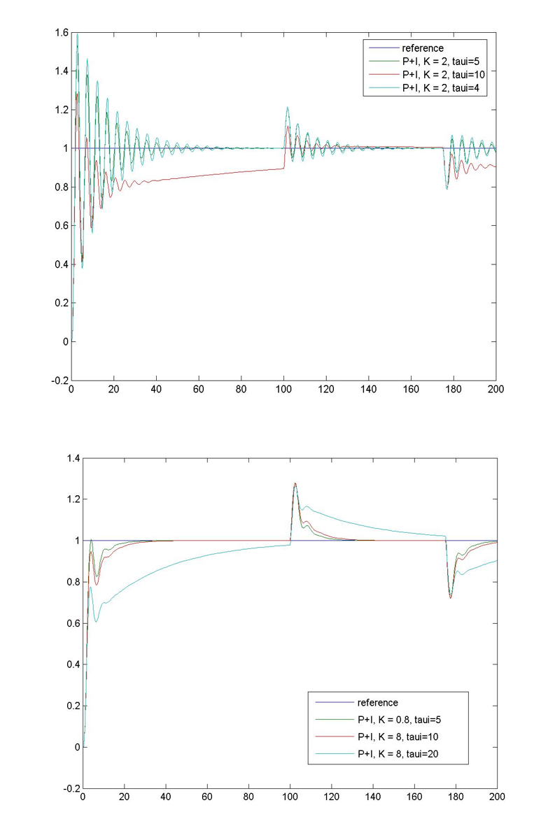
Figure 9‑17 and Figure 9‑18 show the effect of Proportional + Integral Control on the closed loop response of this system – the steady state tracking is seen improved – the steady state error is being integrated to zero. Figure 9‑19 also shows how the changing value of the Integral Time Constant [latex]\tau_i[/latex] affects the system closed loop response, this time in presence of a disturbance. The smaller the value of the Time Constant [latex]\tau_i[/latex], (i.e. the larger the value of the Integral Gain [latex]K_i[/latex]), the stronger the Integral effect – the error is integrated to zero faster, but there are more oscillations.
9.4.1 Effect of Windup in Integral Controller
Let’s discuss now the effect of the Integral Control on the controller output. In an ideal LTI system, the system linear range is infinite. In real life systems, the actuator input can saturate due to physical limitations on its dynamic range – there is a limit beyond which the controller output is truncated. Because the integral controller input is non-zero as long as there is an error in the system, its output tends to reach that limit relatively quickly. Figure 9‑20, left, shows the controller output signal when there is no saturation in it. The system response is linear and shown on the right.
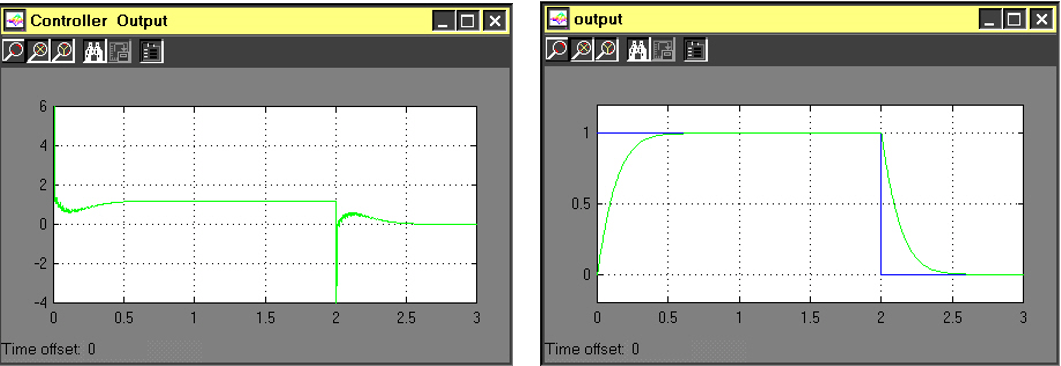
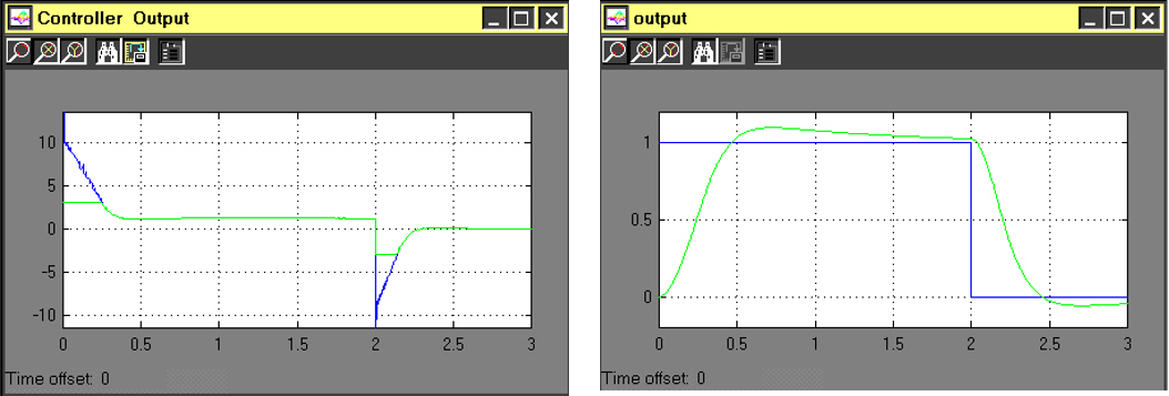
Figure 9‑21, left, shows the controller output signal when there is saturation – shown as clipping of the controller output. When the controller output saturates and the integral action is not switched off, the controller output command still keeps growing because the error signal is still present. Once the system comes out of saturation, the system will try to “catch up“ to that command, and the system output response will show a large overshoot, as a result of the energy stored in the integrator. This is known as a Windup Effect. This is visible in Figure 9‑21, right, as an additional overshoot in the response.
To remedy the problem, a so-called Anti-Windup scheme is implemented, which turns off the integral action as soon as actuator saturation occurs. A simulation of the Anti-Windup scheme is shown in Figure 9‑22.
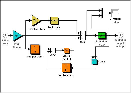
The unsaturated signal represents the controller digital algorithm output, and the saturated signal, U(s), is the actual analog controller output, which stays between some set hard limits. When the system is unsaturated, the anti-windup signal is zero, and the integral action works as intended. When U(s) saturates, an additional loop around the integrator is created, effectively replacing it with a first-order term with an anti-windup time constant.
| [latex]G(s)=\frac{\tau_t}{\tau_t s +1}[/latex] | Equation 9-10 |
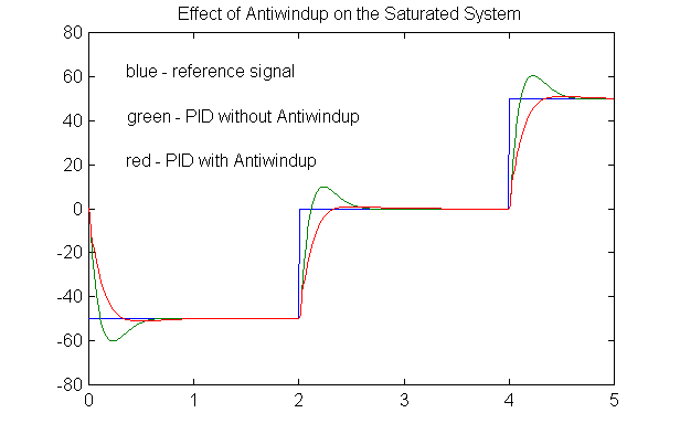
The smaller the anti-windup time constant is in Equation 9‑10, the less effective the integral action is, i.e. the stronger the anti-windup action. Figure 9‑23 shows the effect of Anti-Windup on the response of the PI system.
9.4.2 Summary of Proportional + Integral Control Attributes
Steady state tracking:
- Integral action stronger for small integral time constants
- Integral action increases system type – smaller step errors and ramp errors
- Integral action reduces the effect of disturbance in the steady state
Dynamic tracking:
- Integral action introduces increased system oscillations, – possible instability
- Possible saturation in the controller (windup) – Anti-Windup scheme
