Chapter 3
3.2 Signal Flow Graphs
3.2.1 Introduction
We have just demonstrated that transfer functions of systems represented by block diagrams can be found by applying the rules of block diagram algebra and their reduction. A simpler approach referred to as “Signal Flow Graphs” will be now introduced. The theory of flow graphs follows the theory of solutions of sets of algebraic simultaneous equations – both the block diagrams and signal flow graphs are graphical representations of algebraic equations. In 1953 Samuel J. Mason (1921-1974), working at M.I.T., published a paper in which he stated the gain formula now used to determine transfer functions from signal flow graphs.
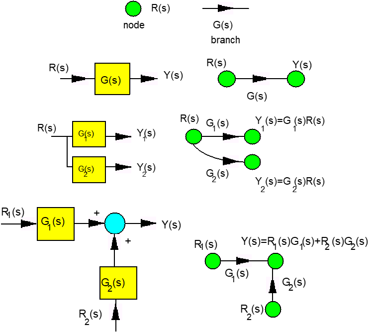
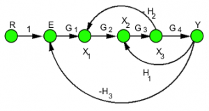
Mason’s Gain formula is basically a short-hand representation of the Cramer’s Rule that is used to solve sets of algebraic equations. Block diagrams consist of blocks, summers, take-off points and signals with arrows indicating a direction of a signal flow. Signal flow graphs are much more succinct and only include nodes for signals and branches for gains. Any signals entering a node are assumed to be added or subtracted, as indicated by the polarity of the branch gain – thus for the incoming signals, the node acts as a summer. Any signal leaving the node is assumed to carry the value of the signal represented by that node – thus the node also acts as a take-off point, for all outgoing signals. Figure 3‑6 shows basic equivalencies between a block diagram and a signal flow graph. Using these basic definitions, the block diagram shown in Figure 3‑1 can be re-drawn as a signal flow graph shown in Figure 3‑7.


3.2.2 Introduction
Consider again the block diagram example shown in Figure 3‑1, where we want to calculate the I/O relationship, the transfer function [latex]G(s) = \frac{Y(s)}{R(s)}[/latex]. An alternative to a tedious block diagram reduction is to consider algebraic equations that are represented by this block diagram, and to apply the Cramer’s rule of solving sets of simultaneous algebraic equations. Recall that the Cramer’s Rule is as follows:
 |
Equation 3‑1 |
|
|
Equation 3‑2 |
In Equation 3‑2, [latex]\Delta[/latex] is defined as the Main Determinant of the set of linear equations shown in Equation 3‑1 and [latex]\Delta_{i}[/latex] is defined as a co-factor of the variable [latex]x_{i}[/latex]. Algebraic equations describing the block diagram in Figure 3‑1, or its equivalent signal flow graph in Figure 3‑7, can be written up as:
[latex]E = R - H_{3}Y[/latex]
[latex]X_{1}= G_{1}E - H_{2}X_{3}[/latex]
[latex]X_{2} = X_{1}G_{2} + H_{1}Y[/latex]
[latex]X_{3} = X_{2}G_{3}[/latex]
[latex]Y = G_{4}X_{3}[/latex]
They can be re-written in a matrix form as:

The solution for the output signal, Y, can be then found, according to Equation 3‑2.
 |
Equation 3‑3 |
In Equation 3‑3, the Main Determinant of the equation set, and also of the system represented by the block diagram, can be found, following the rules of matrix algebra:

Similarly, the Co-factor for variable Y can be found as:

Finally, the transfer function of the system can be found:
[latex]Y = \frac{\Delta_{\gamma}}{\Delta} = \frac{RG_{1}G_{2}G_{3}G_{4}}{1+G_{1}G_{2}G_{3}G_{4}H_{3} - G_{2}G_{4}H_{3} + G_{2}G_{3}H_{2}}[/latex]
[latex]Y = \frac{Y}{R} = \frac{G_{1}G_{2}G_{3}G_{4}}{1+G_{1}G_{2}G_{3}G_{4}H_{3} - G_{3}G_{4}H_{3} + G_{2}G_{3}H_{2}}[/latex]
This is of course identical with the solution derived through the block diagram reduction. What follows is called the Mason’s Gain formula, and it is a short-hand notation of the Cramer’s Rule result. The Mason’s Gain formula defines a few simple-to-follow rules that allow us to write the transfer function of the system by inspection, without going through solving the algebraic equations describing the signal flow (or block diagram).
3.2.3 Mason’s Gain Formula
The Mason’s gain formula is written as:
| [latex]G(s) = \frac{\sum_{i}P_{i}\cdot \Delta_{i}}{\Delta}[/latex] |
Equation 3‑4 |
where [latex]\Delta[/latex] is the Main Determinant of the system described by a signal flow graph. The system characteristic equation is then [latex]\Delta (s) = 0[/latex]. The Main Determinant is defined as:
| [latex]\Delta = 1 - \bigg( \sum_{k} L_{k} \bigg) + \bigg( \sum_{k} L_{i}L_{j} \bigg) - \bigg( \sum_{k} L_{l}L_{n}L_{m} \bigg) + ...[/latex] | Equation 3‑5 |
Note that the Main determinant always starts with a 1, and the signs in front of all the remaining terms follow a checker-board pattern, starting with a negative sign (i.e., -, +, -, +, etc.)
Other terms appearing in the formula are defined as forward paths [latex]P_{i}[/latex] and their Co-factors [latex]\Delta_{i}[/latex], and loops [latex]L_{i}[/latex].
A Loop is defined as any closed signal path within the signal flow graph, as long as none of the loop components (neither a node nor a branch) is traversed twice.
[latex]\sum L_{k}[/latex]– this expression corresponds to a sum of all loops in the signal flow;
[latex]\sum L_{i}L_{j}[/latex] – this expression corresponds to a sum of products of all non-touching loops taken two at a time;
[latex]\sum L_{l}L_{m}L_{n}[/latex] – this expression corresponds to a sum of products of all non-touching loops taken three at a time, etc., etc…..
[latex]P_{i}[/latex] – this expression corresponds to a path in the signal flow, defined as any way through the signal flow graph from the input to the output which does not go through any nodes or branches twice.
[latex]\Delta_{i}[/latex] – this expression corresponds to a cofactor of a given path – it is created from the main determinant by dropping from it all expressions containing loops touching the given path.
When the Mason’s gain formula is applied to the signal flow graph from our example in Figure 3‑7, the result is as follows:
[latex]L_{1} = G_{3}G_{4}H_{1}[/latex]
[latex]L_{2} = -G_{2}G_{3}H_{2}[/latex]
[latex]L_{3} = -G_{1}G_{2}G_{3}G_{4}H_{3}[/latex]
[latex]\Delta = 1 - ( L_{1} + L_{2} + L_{3})[/latex]
[latex]P_{1} = G_{1}G_{2}G_{3}G_{4}[/latex]
[latex]\Delta_{1} = 1[/latex]
[latex]G(s) = \frac{P_{1} \cdot \Delta_{1}}{\Delta} = \frac{G_{1}G_{2}G_{3}G_{4}}{1+G_{1}G_{2}G_{3}G_{4}H_{3} - G_{3}G{4}H_{1} + G_{2}G_{3}H_{2} }[/latex]
Of course, this result is identical with the ones obtained before, through block diagram reduction, and through Cramer’s Rule.


